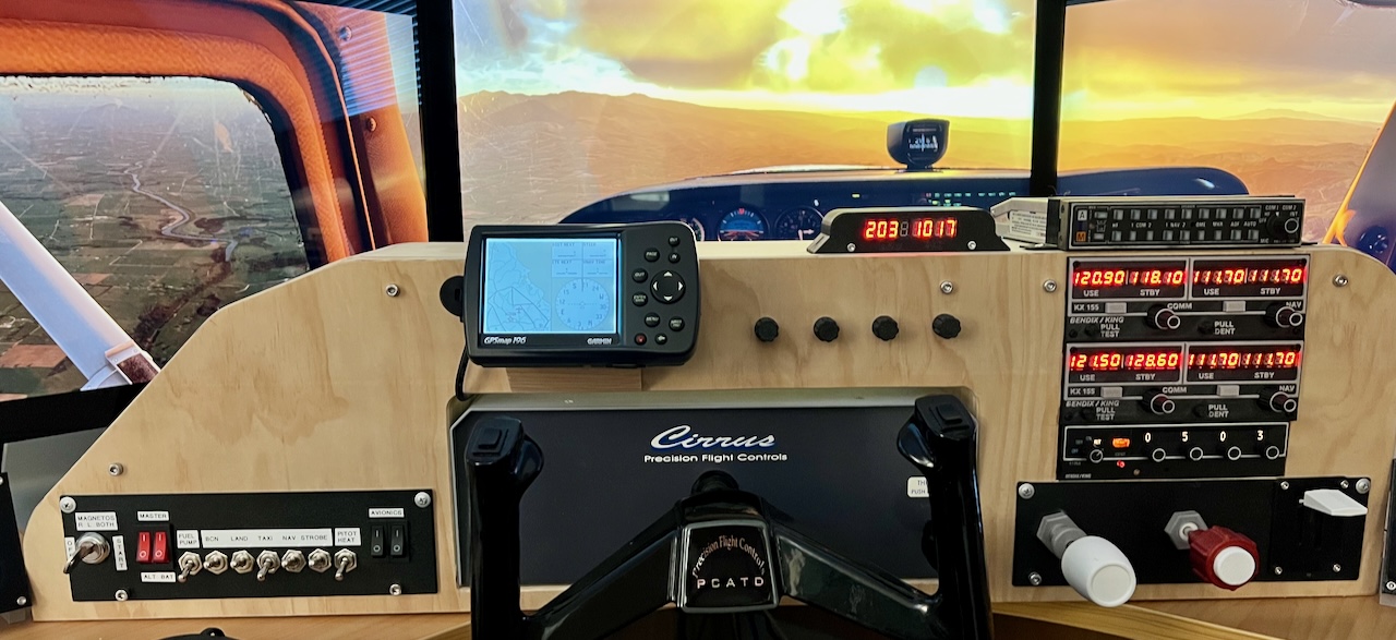
Cessna 172 Transponder
I learned to fly with “steam gauges” in Piper Tomahawks then Cessna 172s of various versions which explains my choices in flight instruments on my panel. Included in this era of aircraft is the King KT76A Transponder. With the new requrement for ADSB capable transponders there are a lot of these old units for sale. I decided to use a real transponder and replace the electronics with a custom USB HID device interface. For the controller, I use the Raspberry Pico which I use for all my projects these days. Here is my discription of this project including the assets you can download and use for non-commercial purposes.
DISCLAIMER - This project is tested on Intel & Arm Mac and Windows (Linux is supported but not tested). It is theoretically possible to get this transponder working on Microsoft Flight Simulator but I haven’t researched that option.
Transponder Electronics
Similar to the Flight Radio, the goals of the electronics part of this project were:
-
Provide a good simulation experience
-
Be affordable
-
Able to be assembled by anyone with reasonable soldering skills (no surface mount components)
As with the Flight Radio, the USB HID device leverages the same X-Plane dedicated plug-in called FlightControls.
Of corse the software work builds on the great work from those that came before. This includes the circuitpython project, PJRC (PaulStoffregen) and Jorg Neves Bliesener (X-Plane plugin).
The two sided PCB is shown on the right (Panel Adapter & USB Controller PCB). This is my third revision which is the one I use in my panel. I tried to make it flexible in the way you power the panel lamps.
I kept the original lamps instead of replacing them with LEDs to make it as original as possible. If a bulb fails it is still possible to get replacements.
I included a DC-DC step up circuit to power the panel lamps however this was a bad idea. It would need more power from the USB cable than was available. So I use the Power Jack configuration option to connect a 12Vdc barrel jack wall adapter for the lights.
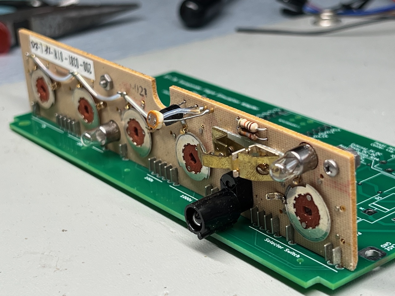
From the photo (Transponder USB HID Adapter PCB) showing the top side of the unit assembly, you can see that the original front panel of the transponder is retained. This includes the knobs, ident button and lights. I wanted it to operate and look exactly as it did in the real aircraft panel.
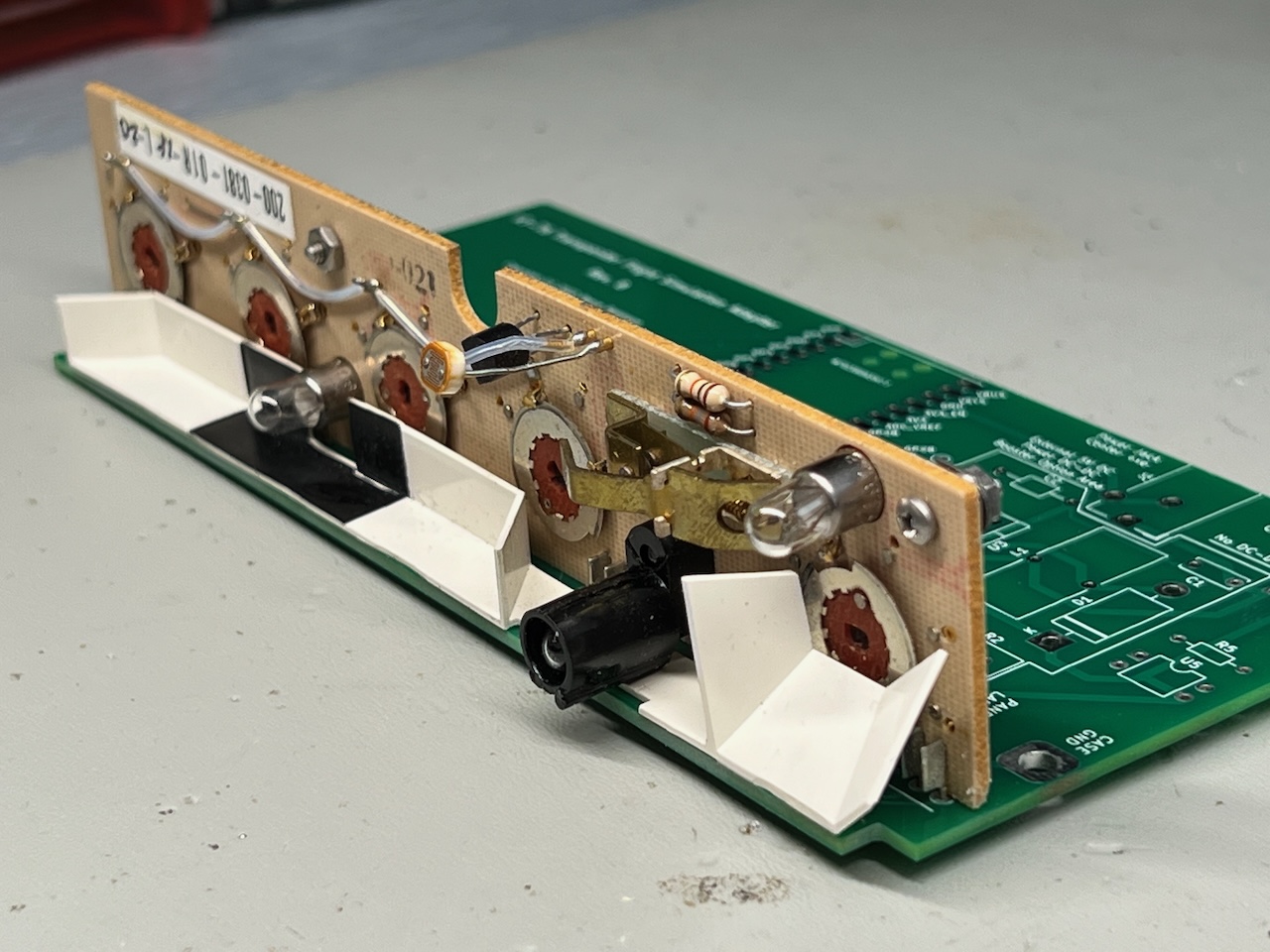
The PCB was designed to be a drop-in replacement for the main radio controller board which is compatible with the front panel riser board and mounting positions of the enclosure. The pin spacings on the riser board were measured and matching PCB holes provided to connect the circuits. Alignment holes for the white plastic lamp light modifiers are also provided for re-mounting.
In the photo (PCB Interconnect View) you can see some of the original riser pins connected to the new controller PCB.
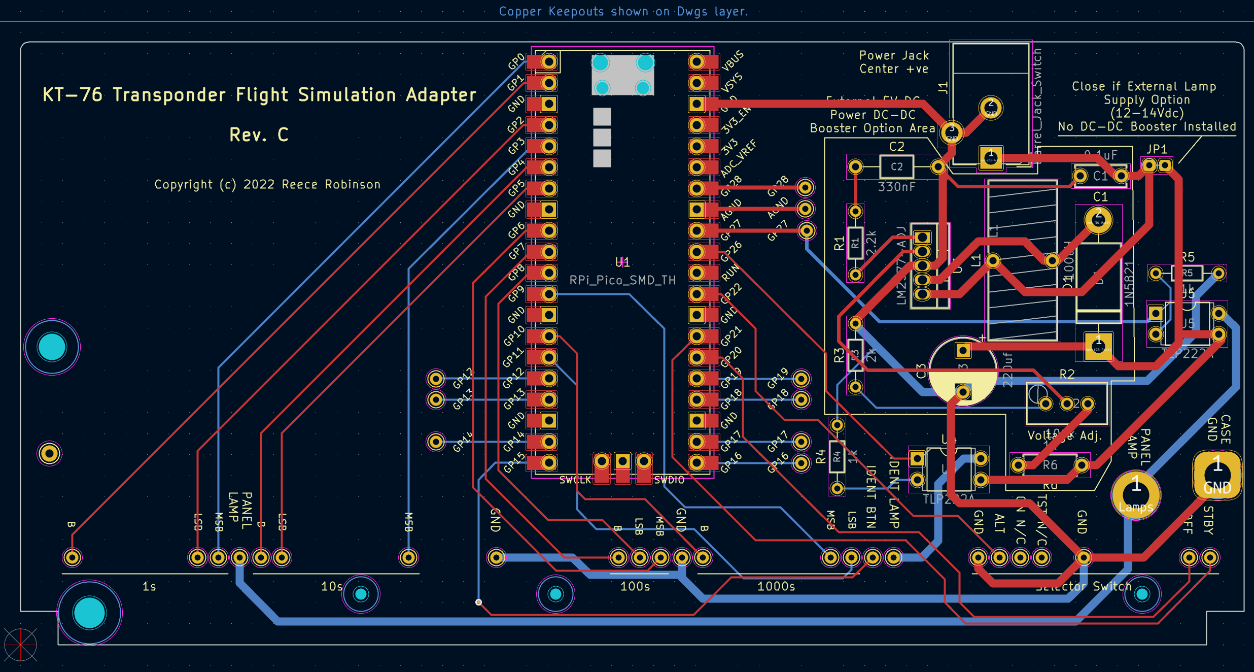
Panel Adapter & USB Controller PCB
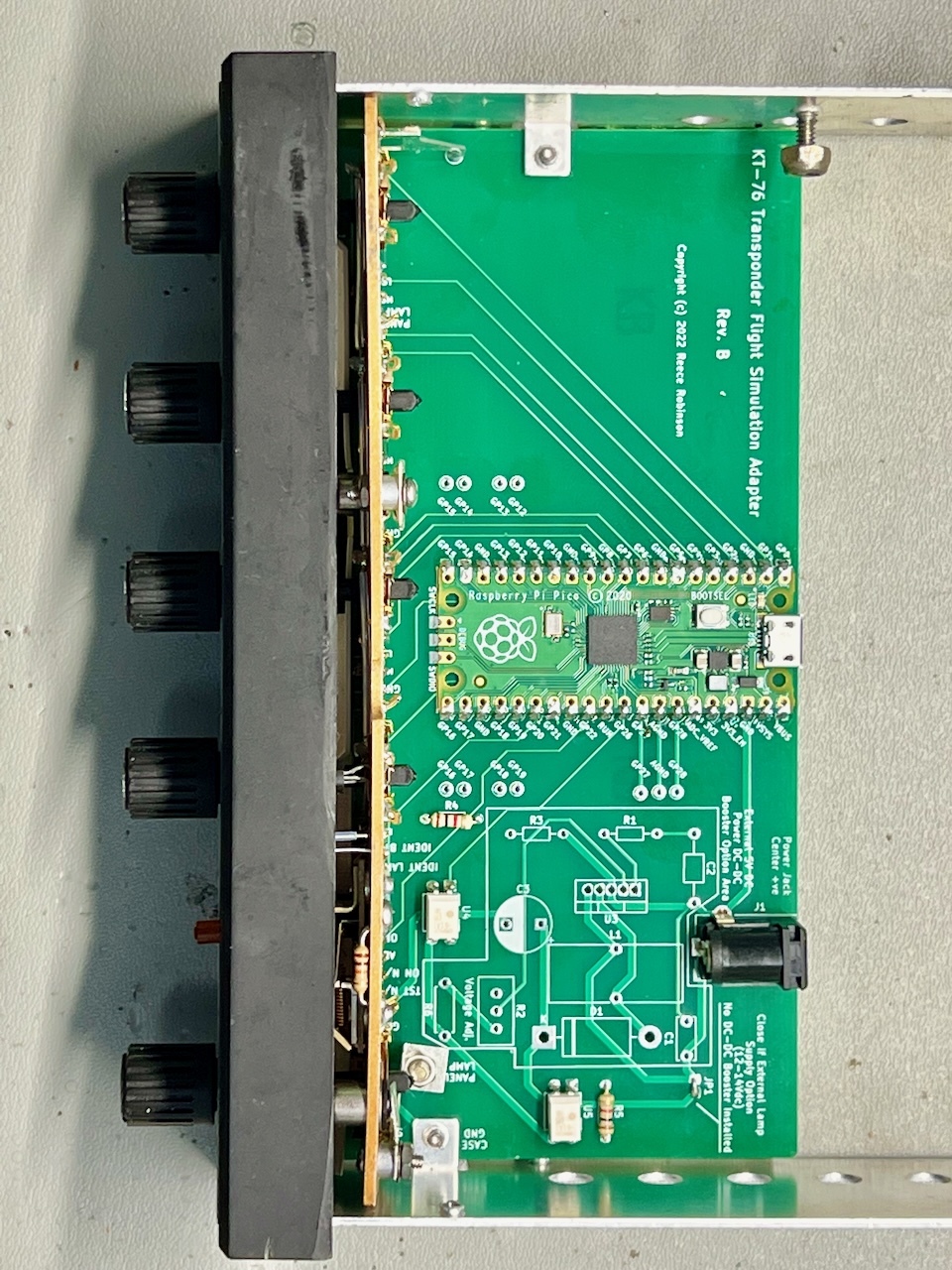
Transponder USB HID Adapter PCB
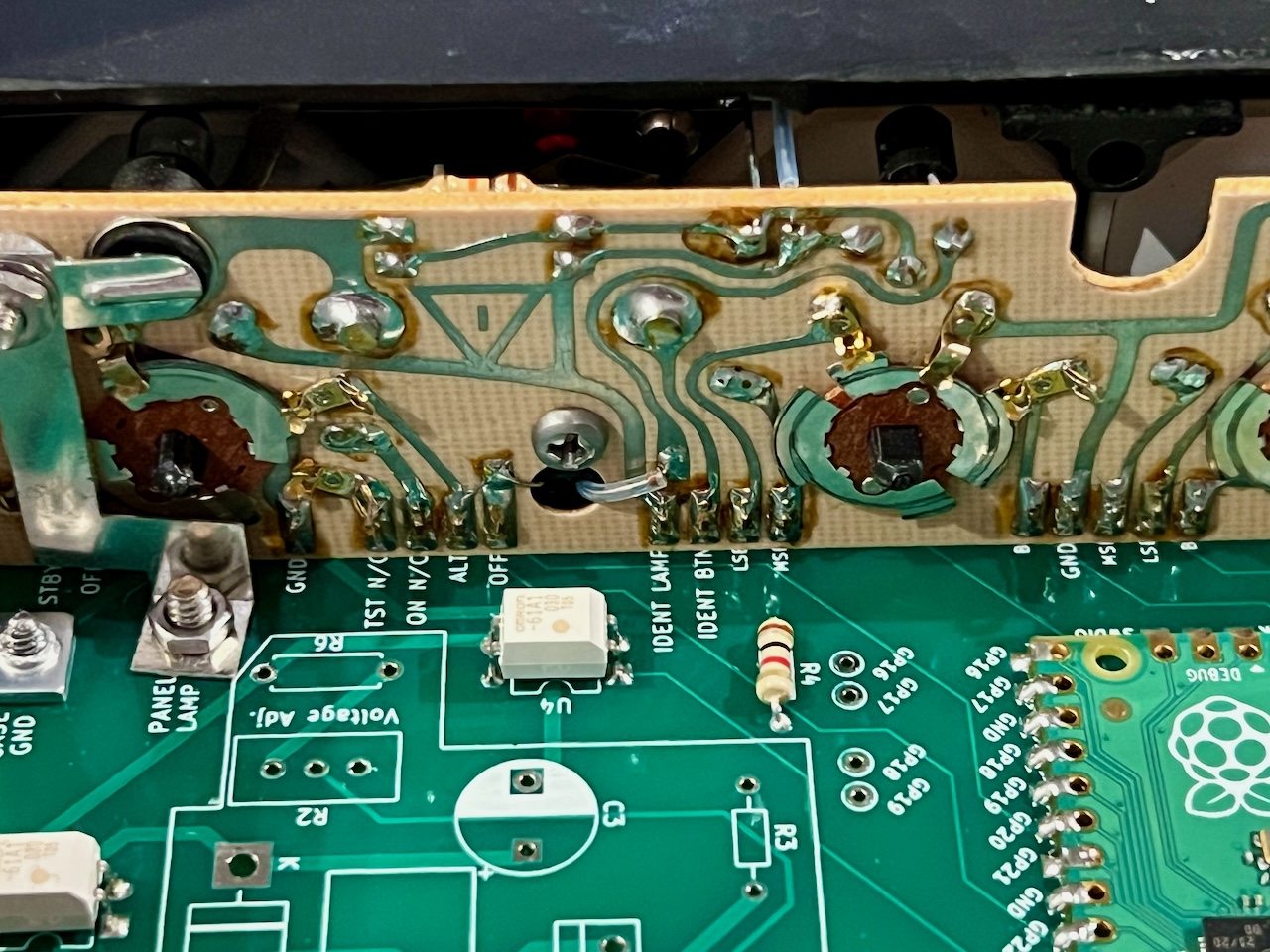
PCB Interconnect View
Transponder Software
The software required to realise this project includes:
-
the firmware to read the selected Sqwark Code, Mode selector and Ident button as well as control the panel lamps.
-
an X-Plane plug-in to communicate with the transponder (custom HID device) and interface with the flight simulator.
The next four sections provide more detail.
Firmware
The firmware requirements were met by using circuitpython... well almost. I did however need to submit a patch to that project to support custom HID devices. But once that was accepted, circuitpython had all the functionality needed.
The firmware presents the transponder as a custom USB HID device to the flight simulation host computer. The X-Plane plugin facilitates communication to integrate the transponder with the simulator.
X-Plane Plugin
The other part of the software is the X-Plane plugin that works with the transponder HID device. This plugin is largely based on the project created by PaulStoffregen & Jorg Neves Bliesener and is used to communicate between the transponder firmware and the flight simulator. Input values are sent to the simulator and lamp illumination state received and used to control the orange activity lamp and the panel back light.
I am a Mac user (that is a big reason I use X-Plane 😉) so I have compiled and tested the plugin on my machine. There was a bug in the original project that I fixed in my fork of the codebase. Using Ubuntu Linux, I compiled the linux and windows versons which are included in the download. The windows version has been tested on Windows 10 Home. The linux version is not tested as I don’t have the hardware for it. If you run X-Plane on Linux I would love to hear from you if you get that version working or not?
To install the plugin unzip the attached plugin archive file in the X-Plane plugins directory. The “FlightControls” folder should end up in the X-Plane plugins directory.
If there is enough interest I will provide the source code of the plugin so anyone can help with the builds for the various platforms.
Note: If the macOS Gatekeeper is blocking the plugin, you can bypass Gatekeeper for this specific instance.
1. Open Terminal:
You can find Terminal in Applications > Utilities.
cd /path/to/X-Plane/Resources/plugins/FlightControls
2. Navigate to the Plugin Directory:
Use the cd command to navigate to the directory containing the mac.xpl plugin. For example:
xattr -d com.apple.quarantine mac.xpl
Prepare the Transponder
Before proceeding you first need to do the following:
-
Remove the control knobs and front panel from the unit. Be carerful, this is old technology and may be fragile. Also remove the white plastic lamp reflector from the main PCB. This has three plastic posts that retain it in place. Try to remove this so you keep the plastic posts as the new PCB has holes for these to ensure they stay in the right position.
-
Remove the original radio PCB. This involves removing the PCB assembly from the metal case and de-soldering the secondary panel riser board from the main PCB. Be carerful to not damage the pins. You can discard the old main PCB.
-
Verify that all the rotary octal encoder mechanisms are un-damaged and serviceable. I noticed in one unit I used had a broken retaining pin in one of the rotary discs that ment there was some play in that digit selector.
PCB Assembly
| Designator | Value | Qty |
|---|---|---|
| J1 | Barrel Jack Switch | 1 |
| JP1 | Jumper to select 12V supply option | 1 |
| R4, R5 | 1k | 2 |
| U1 | RPi Pico | 1 |
| U4, U5 | TLP222A | 2 |
Assemble the circuit board starting with the passive components and then add the Pico. I like to solder the Pico directly to the PCB, however there is enough room for you to use header pins.
Once the components are placed, connect and solder the front riser board. There is only one way to insert it.
Note: The controller board is mounted up-side-down. That is, the front panel riser pins should be oriented to be at the TOP.
Add the white plastic lamp reflector to the PCB. Try to use the original mounting posts with the PCB holes provided.
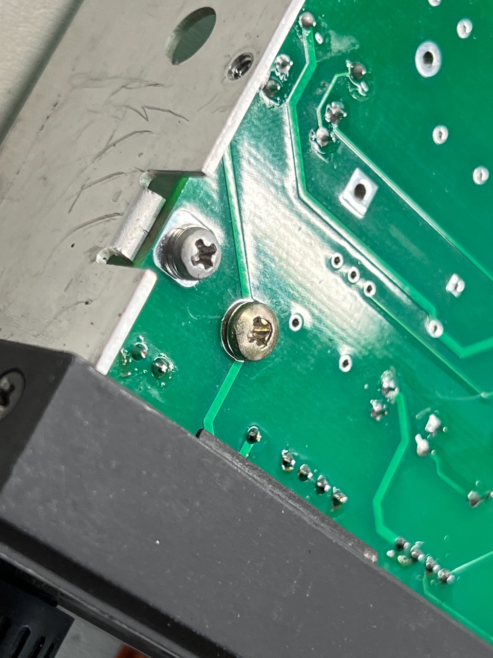
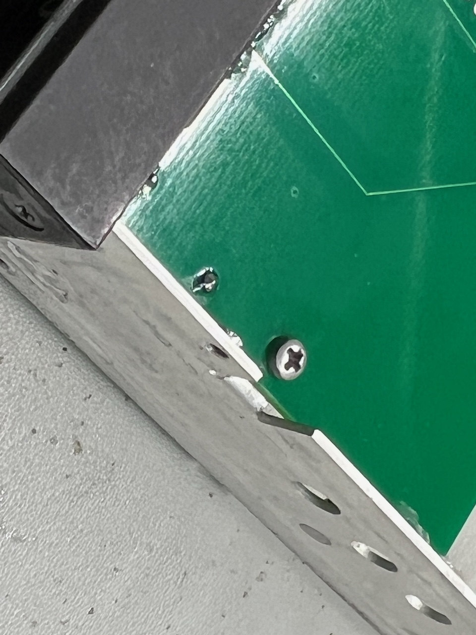
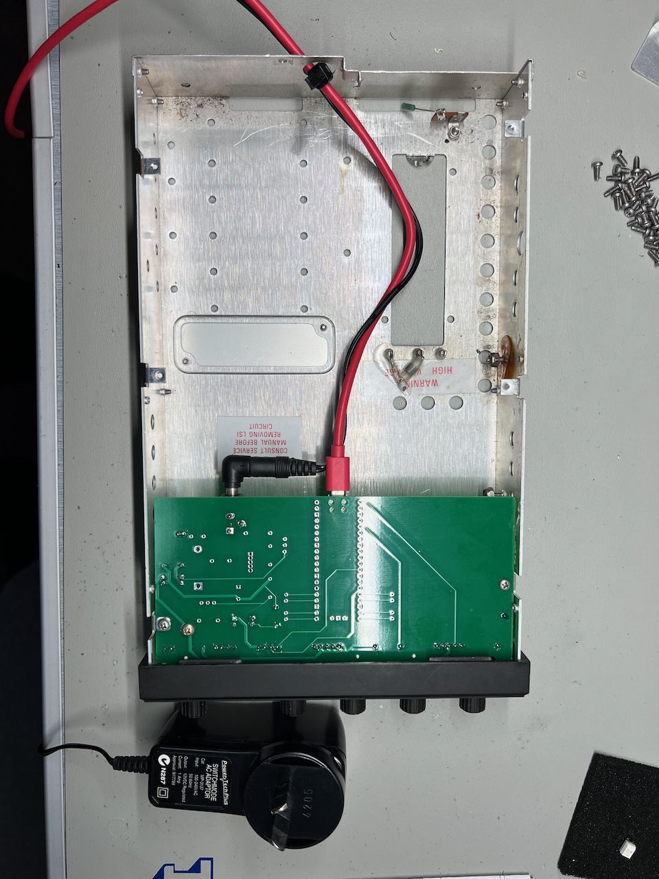
Re-unite the front controls assembly with the riser PCB and place the hole assembly into the aluminium metal case. The mounting screw holes have been replicated in the new PCB so use those to secure the assembly.
Connect the USB cable and 12Vdc power supply using a convenient hole in the back side of the aluminium case.
Mount the transponder into your panel. (see photo below for my configuration).
Assembly Photos
Panel Mounting
