
Cessna 172 Flap Control
As a Cessna 172 pilot I am frustrated by the lack of stability of potentiometer based flap controls. Passive electronic components combined with A/D conversion, introduce noise in the signal that shows up in the cockpit as jitter in the flap lever! I find this issue detracts from my enjoyment flying my virtual aircraft.
To solve this issue I created a Flap Control based on how a real Cessna 172 flap control works, that is, using microswitches to determine the selected flap setting. This work is based on this project from Allan Glen. I have modified the parts for my application. I don’t have a laser engraver so I did not bother with markings on the faceplate. My goal was to have a Flap Control that operated just like a real Cessna 172. If you do have the tools and knowhow, then Allan Glen has the details on his website. I won’t repeat them here.
Flap Control Details
This flap control has four positions for 0, 10, 20 & 30 degree settings. The position of the flap lever is encoded using three microswitches.
To interface this device to the flight simulator, a microcontroller like the Arduino or Raspberry Pico can be used. In my case I use an Arduino Mega 2560 microcontroller and Air Manager to interface with X-Plane. This should also work with Microsoft Flight Simulator but I have not tested that.

Parts List
The following is a list of parts needed to build the Flap Control:
The 3D printer parts are printed in three groups based on the filament colour and type i.e. grey, black and white. I used white ASA filament for the Flap Handle and Position Indicator as that produced a higher quality look and feel. The remaining parts were printed in PETG.
Note: Included in the zip download is a second shorter set of side pieces. I included these because my flight panel is 12mm thick and these short side pieces ensure the flap lever and position indicator protrude the appropriate amount when mounted. If you use a thinner panel like metal or thin MDF then use the longer “regular” size sides.
Assembly
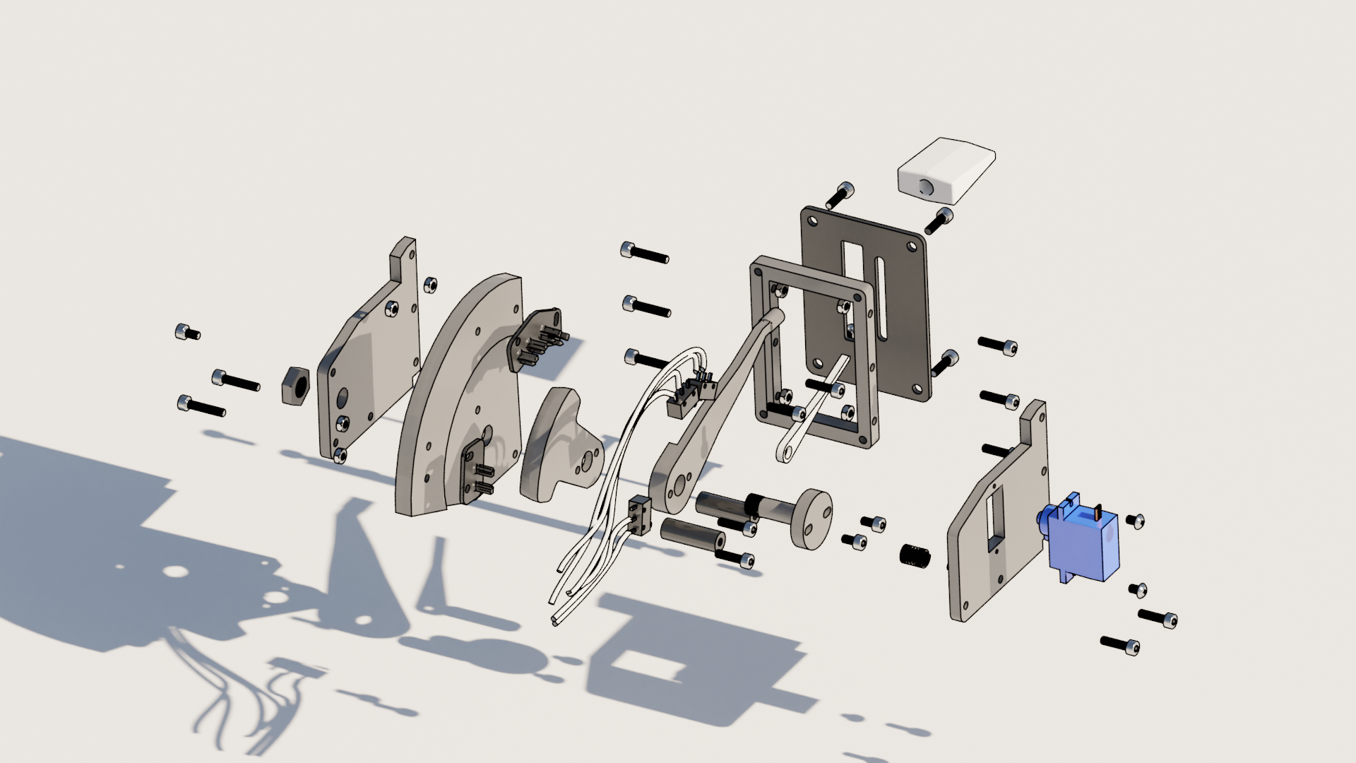
To help visualise the assembly of the Flap Control I have included below some exploded views for reference.
Position Indicator Mount
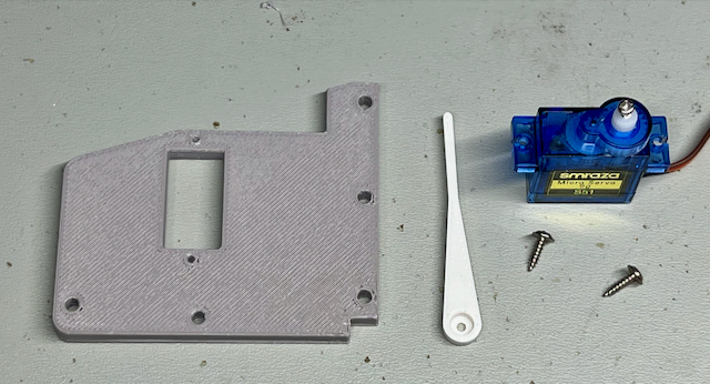
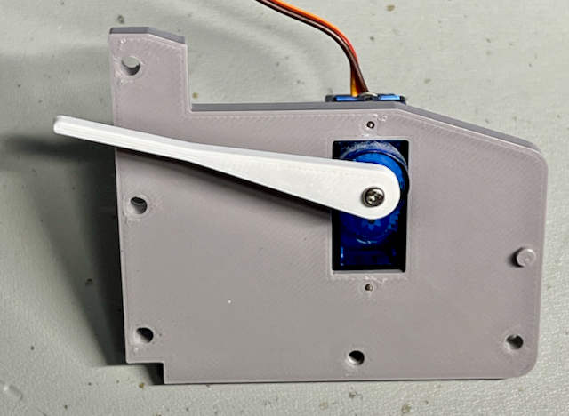
Assemble the position indicator mounting. Use the self-tapping screws provided with the servo to mount the unit in the rectangular opening. Screw holes are provided top and bottom of the opening and should line up with the servo mounting holes.
Switch Mount Base Plate
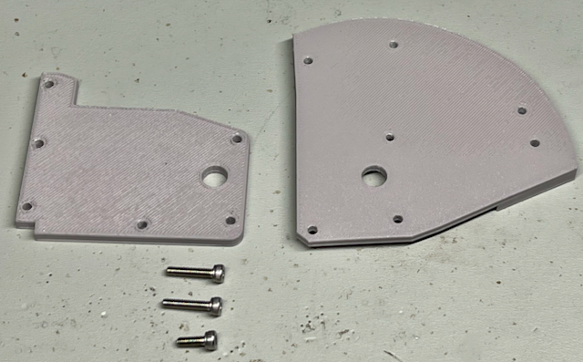
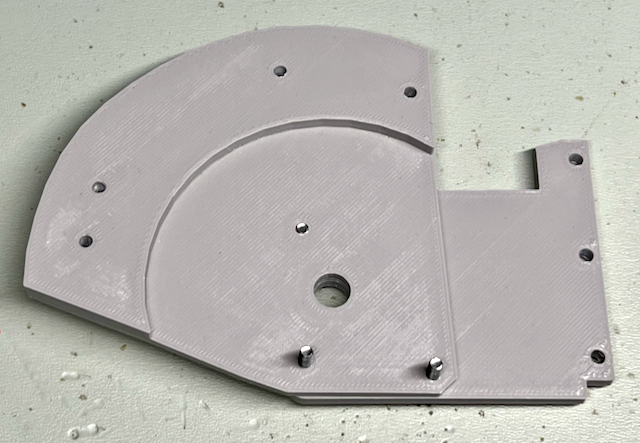
Assemble the switch mount base plate next. The bottom two M3 bolts protrude from the assembly, these will be used for attaching the two spaces later.
Hardware:
2 x M3 14mm
1 x M3 8mm
Flap Control Lever
Assemble the flap control lever next. Rotate the three parts to line up the holes so that the arrangement looks like the finished image.
Hardware:
2 x M3 14mm
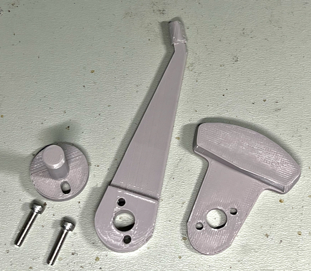
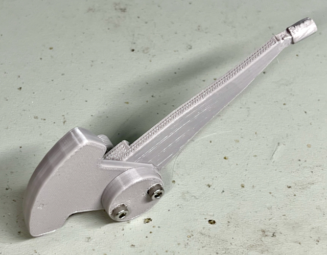
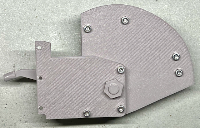
Join Side to Flap Control Lever
Join the two sub assemblies as shown. Use the 3D printed nut to secure the lever assembly. This should be finger tight to provide some friction to the lever operation.
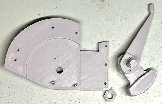
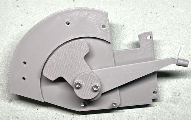
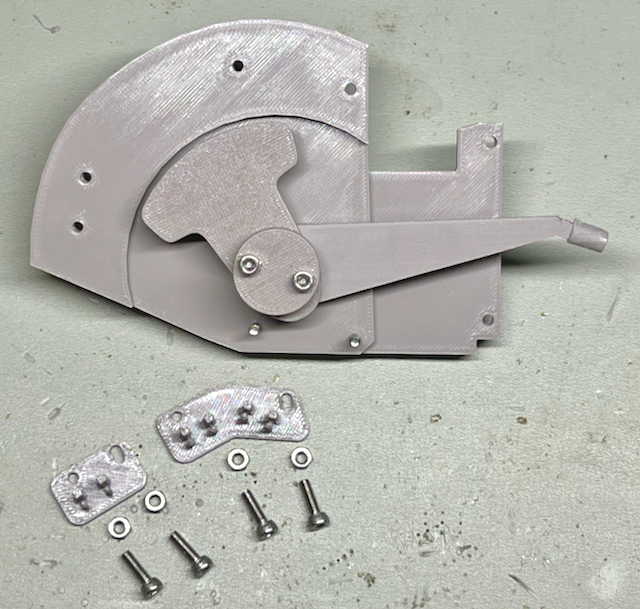
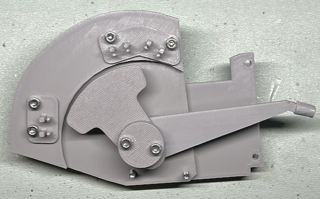
Add Microswitch Holders to Base Plate
Each holder has a slotted hole to provide a small amount of adjustment to the position of each microswitch. Fasten the M3 nuts to ensure the holders don’t move over time with use.
Hardware:
4 x M3 10mm
4 x M3 nut
Add Spacers
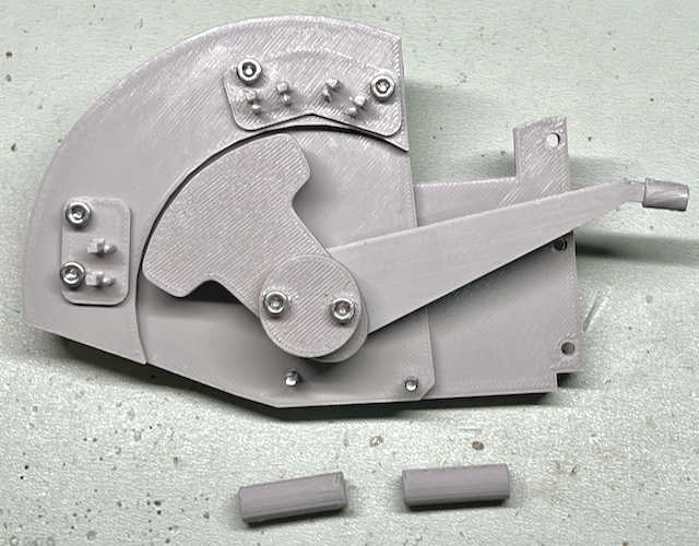
Twist the spacers on to the two M3 bolts at the bottom.
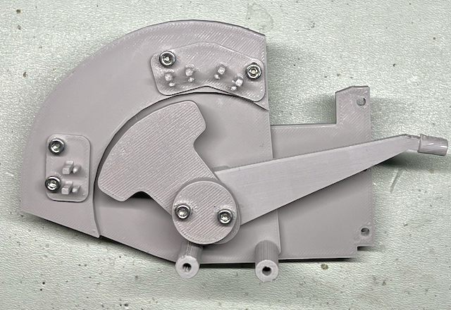
Join the Two Sides
Add the tension spring over the rear M3 bolt head of the Flap Control Lever assembly. The other side of the spring should be positioned over the nub on the adjacent side.
Hardware:
2 x M3 12mm
1 x Spring 1/4” x 13/32"
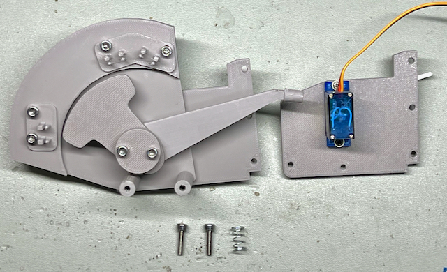
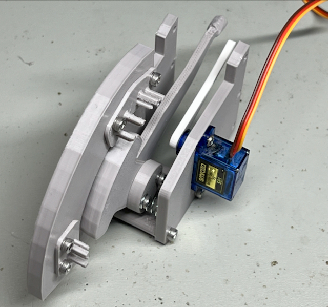
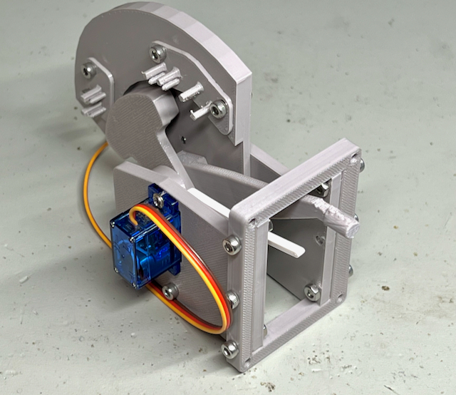
Add the Front Frame.
Add the M3 nuts for the top and bottom row. This helps provide mechanical strength to the unit.
Hardware:
2 x M3 14mm
3 x M3 12mm
1 x M3 10mm
4 x M3 nut
Note: The thicker side of the frame needs to be on the side that has the microswitch mounts.
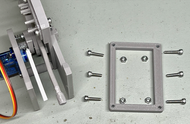
Add the Face Plate and Flap Handle
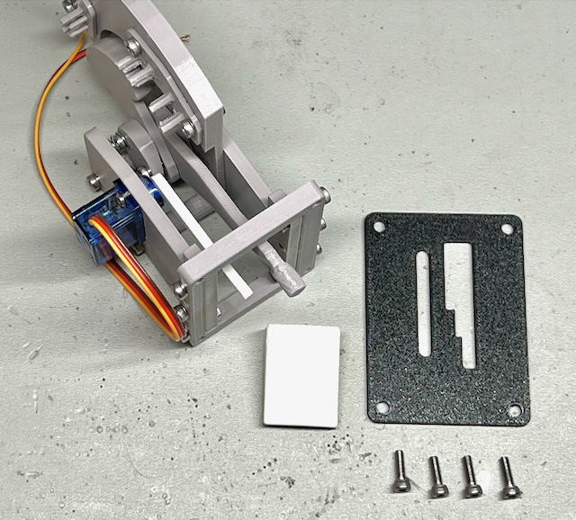
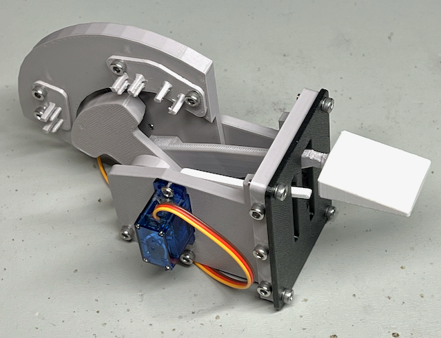
Depending on the thickness of your flight panel, choose the appropriate M3 bolt length.
Note: Carefully push the flap handle on to the end of the flap lever. Ensure you support the neck near the end of the lever to avoid snapping it when you apply force.
Hardware:
4 x M3 10mm
Adding the Microswitches & Wiring
Now that the Flap Control has been assembled we can add the three microswitches and wire them.
The flap setting is encoded in the values indicated by each microswitch state ie. open or closed.
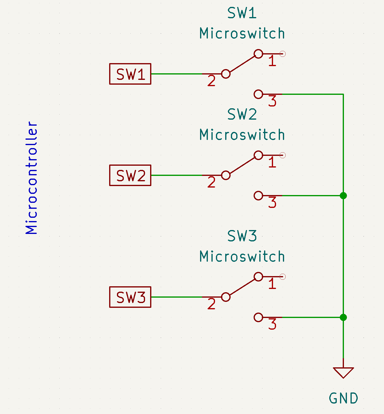
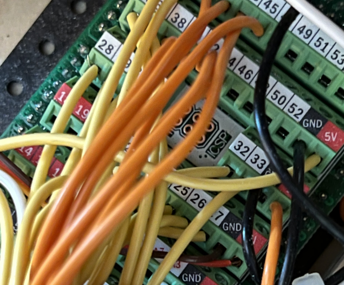
One side of each switch is wired to a digital input of the microcontroller with the inputs configured with pull-up resisters. The other side of each switch is connected to ground.
When the switch is closed the input is connected to ground. So the open state of the switch reads as a 1 or “off" and the closed state reads a 0 or “on”.
The following “truth” table shows how each flap setting is encoded by the microswitches:
| Flap Position | SW1 | SW2 | SW3 |
|---|---|---|---|
| 0° | 1 | 0 | 0 |
| 10° | 0 | 0 | 0 |
| 20° | 0 | 1 | 0 |
| 30° | 0 | 1 | 1 |
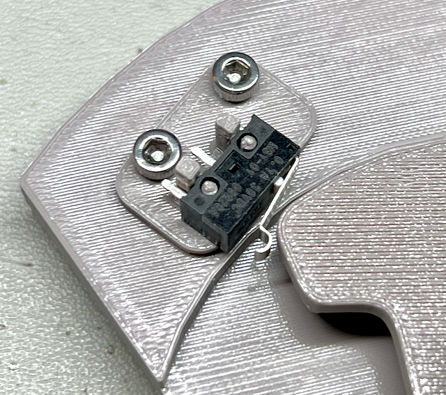
SW 1
It is important that you get the orientation of the microswitch lever correct when mounting them on the Flap Control. For SW 1, which corresponds to the zero degrees flap setting, ensure the simulated roller is oriented as shown here.
SW 2
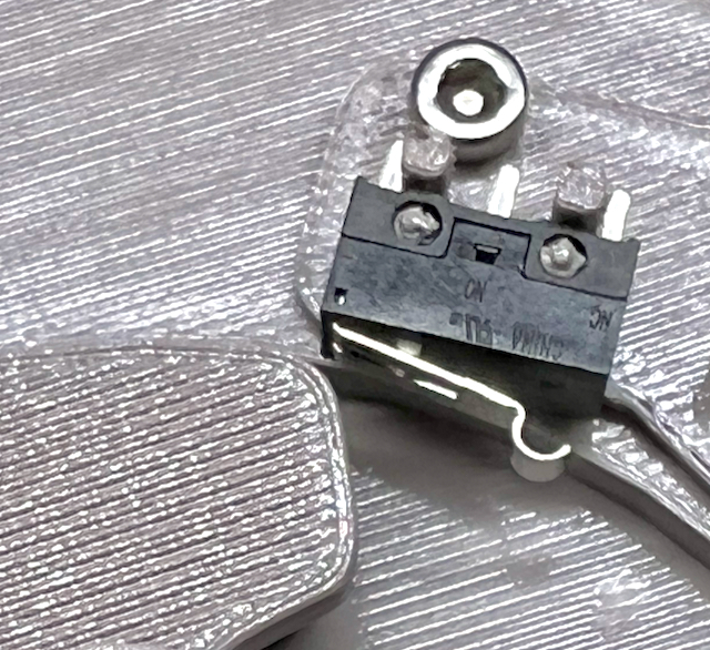
SW 2 is used to differentiate between the 10° and the 20° flap setting. The microswitch orientation is opposite to that of SW1.
SW 3
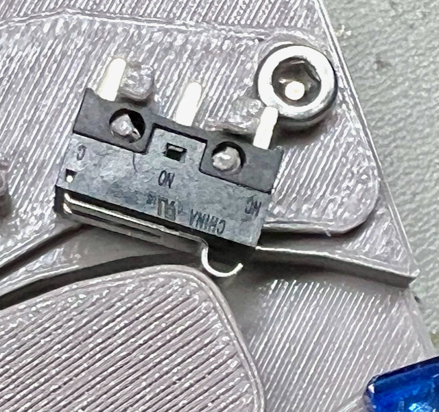
SW 3 orientation is the same as SW 2. It is a tight fit next to SW2 so be careful not to snap the delicate holder posts when setting the switch in place. This microswitch is closed when the 30° flap setting is selected.
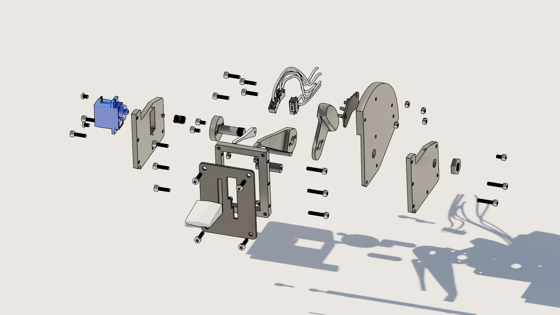
Front Exploded View
This exploded view shows the relative arrangement of parts from a front angle.
Rear Exploded View
This exploded view shows hte relative arrangement of parts from a rear angle.
Software Setup
As I mentioned above, I use Air Manager to interface the Flap Control with X-Plane. We need to configure both the Flap Lever microswitches and the position indicator servo to work with the simulator.
You can modify these scripts to configure the flight sim you use if it isn’t X-Plane.
Flap Lever Script
The following is my Air Manager Lua script for reading the flap setting.
sw_1 = 0
sw_2 = 0
sw_3 = 0

function set_flaps()
    if sw_1 == 1 then
        flaps_pos = 0.0
    elseif sw_1 == 0 and sw_2 == 0 and sw_3 == 0 then
        flaps_pos = 0.33
    elseif sw_1 == 0 and sw_2 == 1 and sw_3 == 0 then
        flaps_pos = 0.66
    elseif sw_3 == 1 then
        flaps_pos = 1.0
    end

    print(flaps_pos)
    xpl_dataref_write("sim/flightmodel/controls/flaprqst", "FLOAT", flaps_pos)
    xpl_dataref_write("172/control_surfaces/flaps", "FLOAT", flaps_pos)
end


function flap_sw_1_callback(position)
    sw_1 = position
    set_flaps()
end
function flap_sw_2_callback(position)
    sw_2 = position
    set_flaps()
end
function flap_sw_3_callback(position)
    sw_3 = position
    set_flaps()
end

hw_switch_add("Flap_switch_1", 1, flap_sw_1_callback)
hw_switch_add("Flap_switch_2", 1, flap_sw_2_callback)
hw_switch_add("Flap_switch_3", 1, flap_sw_3_callback)
Position Indicator Script
This one may need some tuning for your setup. For example there are a few “magic” numbers in the script used to control the start and end of the servo movement range to correspond with the physical limits of 0 and 30 degree flap indication i.e. top and bottom limits.
The following is my Air Manager Lua script for controlling the flap position indicator.
-- Add the servo motor to the script
-- 50 hertz for micro servo 9g S51
-- 0.021 dutycycle initially or no flap extension
pwm_flap_pos = hw_output_pwm_add("Flap Indicator servo", 50, 0.020)

-- In this case the duty cycle ranges from 0.02 to 0.10
-- We have flaps that go from 0 to 1.0 (full extension)
function new_pos(pos)
    print('pos:',pos)
    -- configurable parameters based on the servo being used.
    usable_fraction = 0.21 -- the fraction of the available range of motion for the attached indicator arm.
    start_of_range = 0.018 -- the starting dutycycle. When attaching the indicator make sure it is near the start of the servo range.
    end_of_range = 0.1 -- the maximum dutycycle of the servo.

    dutycycle_range = (end_of_range - start_of_range)

    -- scale the position 0..1 to the dutycycle range 0.02..0.1.
    -- y = m * x + c or y = 0.08 * x + 0.02
    x = dutycycle_range * pos + start_of_range

    -- scale x to a log scale and subtract that from the max dutycycle ie. end_of_range
    y = end_of_range - (dutycycle_range *(math.log(x)/math.log(dutycycle_range))) + start_of_range

    -- scale the result to the usable range of motion for the servo & add the base offset for the start of the range.
    y = (y * usable_fraction) + start_of_range

    -- Clamp values to physical limits.
    if y <= 0.018 then y = 0.018 end
    if y >= 0.028 then y = 0.028 end

    hw_output_pwm_duty_cycle(pwm_flap_pos, y)

end

xpl_dataref_subscribe("sim/flightmodel2/controls/flap1_deploy_ratio", "FLOAT", new_pos)
Enjoy
If you have gotten this far and have successfully built a Flap Control - Well Done! I hope you get as much enjoyment out of it as I do.
If you notice any errors or omissions in this page please let me know so I can fix it. Send an email to flapcontrol@trac-group.co.nz.
Note: This work is free to use for personal enjoyment. All rights are reserved for commercial use.