Cessna 172 Style Flight Radio
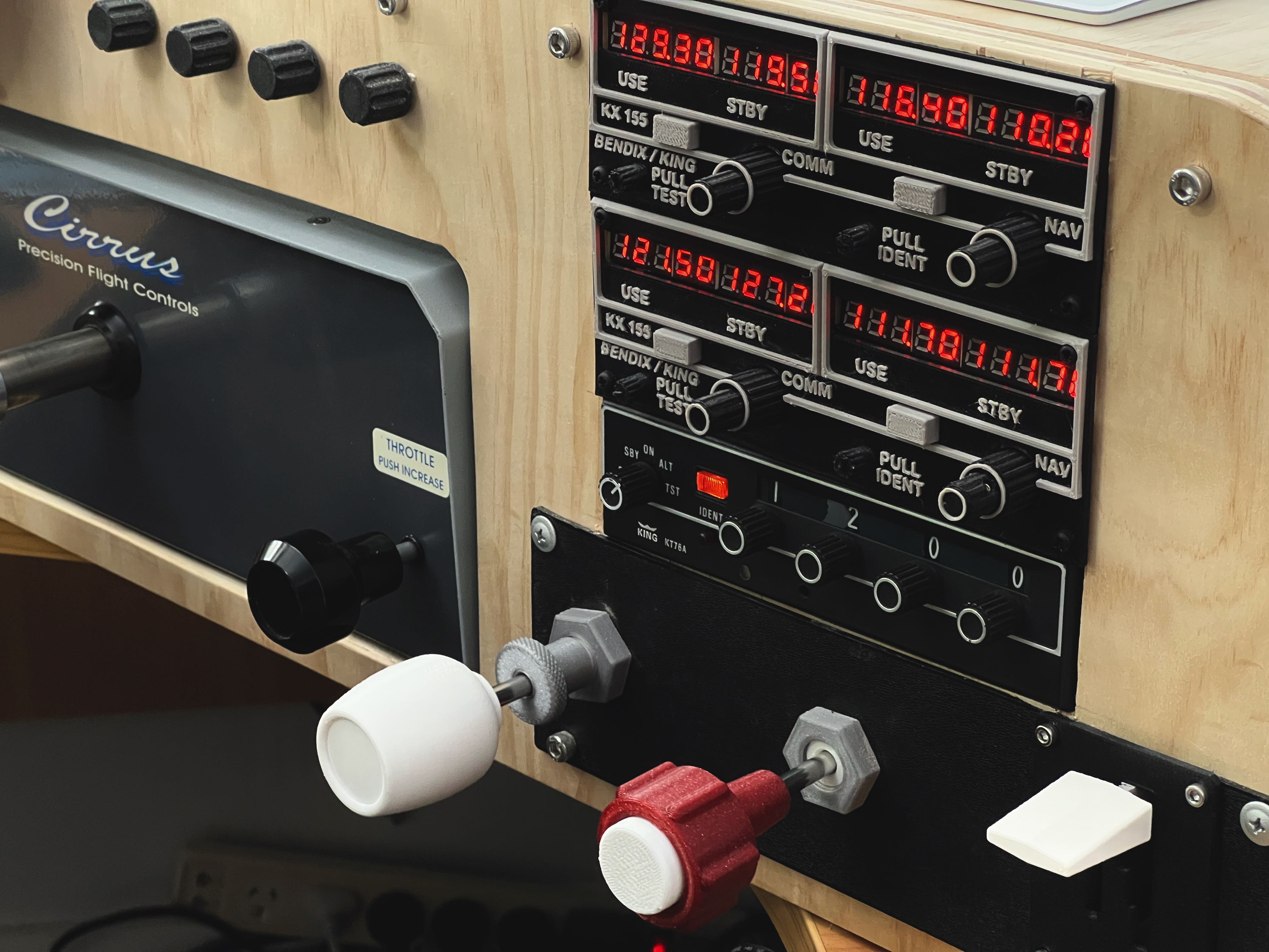
I don’t know why…but for me having a realistic flight radio is the pinnacle of my flight simulation experience after a yoke, pedals and trim wheel! The flight radio is the icing on the flight panel cake. I didn’t want to buy a Logitech simulation radio controller. The layout and operation was not close enough to using a real flight radio that I was used to.
This project also inspired me to tackle the technical challenge of providing direct USB integration into X-Plane via a dedicated plug-in. This one tested my technical ability. However I am please to share the result of that work here.
Of corse the software work I created builds on great work from those that came before. This includes the circuitpython project, PJRC (PaulStoffregen) and Jorg Neves Bliesener (X-Plane plugin).
Now that I have two of these flight radios installed in my flight panel, I really enjoy the added realism.
DISCLAIMER - This project is tested on Intel & Arm Mac, Linux and Windows. It is theoretically possible to get this radio working on Microsoft Flight Simulator but I haven’t researched that option.
Flight Radio Electronics
The goals of the electronics part of this project were:
-
Provide a good simulation experience
-
Be affordable
-
Able to be assembled by anyone with reasonable soldering skills (no surface mount components)
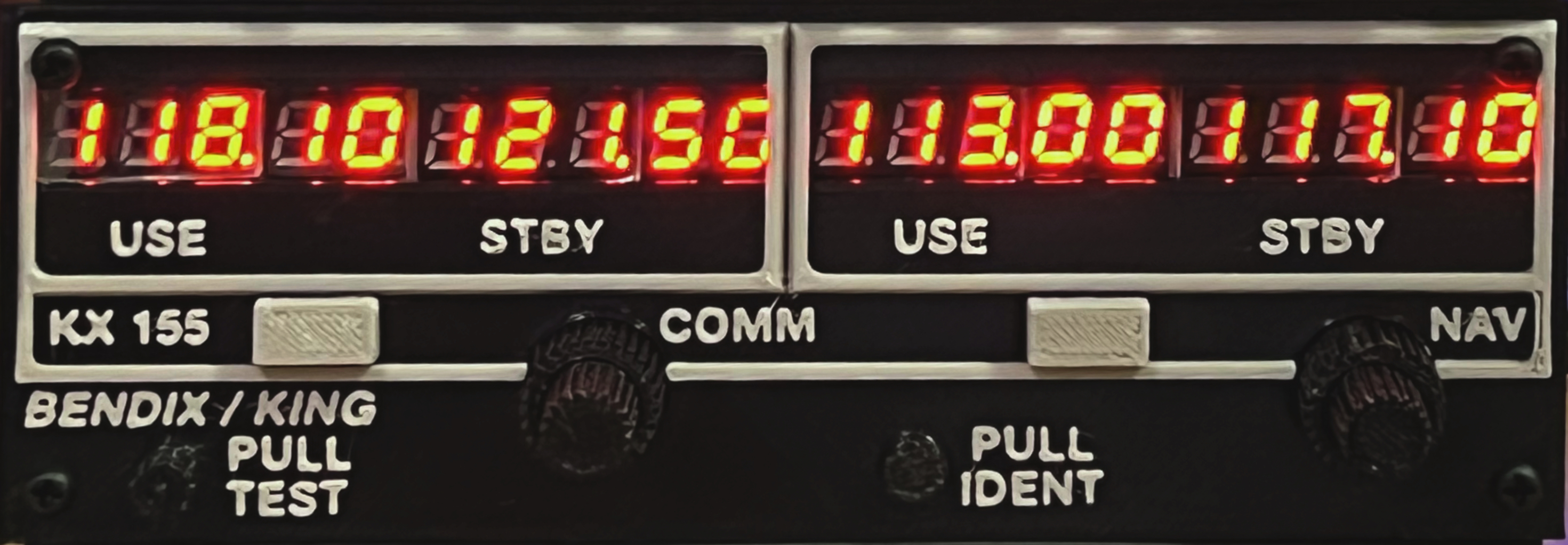
Functionally I wanted it to look and operate as close as possible to a real Bendix/King KX-155 flight radio.
I wanted the physical size of the completed radio to be approximately the same size as the actual Bendix/King KX-155 model. This was important to me as I have integrated a real King KMA Audio Panel and King KT-76 Transponder into my “stack” and wanted the radio to not look out of place.
To achieve this I opted to create a two board design with interconnects (see completed assembly photos 5 & 6). One board contained the displays, drivers, buttons and dual encoders, and the other board hosted the microprocessor. In this case I chose the Raspberry Pico due to its affordable cost and modern capabilities. Two header pin groups form the male side of the board interconnect. These are mounted on the processor board. The corresponding female headers mount to the underside of the display board.
For the frequency transfer buttons I leveraged standard MX keyboard switches. This may be an unusual choice but they provide a satisfyingly nice amount of travel over the dome style press switches.
For radio frequency tuning, I included off-the-shelf dual rotary encoders in this design. I didn’t want to experiement with making my own from two single encoders as seen on the internet. The frequency tuning knobs are the main tactile experience with the flight radio and I didn’t want to compromise the quality of operation. They are not that expensive so it was a no brainer.
The images to the right show the designs of both boards.
The photos to the right and below show the display board (photo 1), the processor board top (photo 2) and processor board bottom (photo 3). The cutout in the processor board is to allow room for the USB cable connector when plugged into the micro usb connector of the Pico. The holes near the cutout are for attaching cable strain relief cable ties (see photo 4).
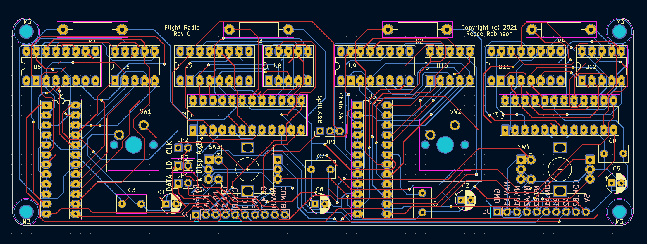
Display PCB
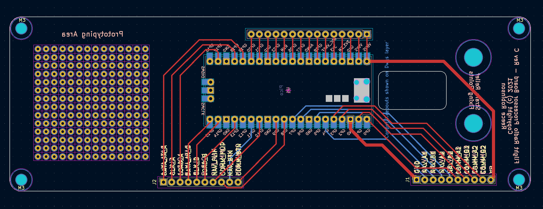
Processor PCB
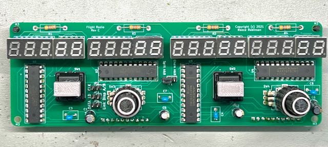
Photo 1 - Display Board
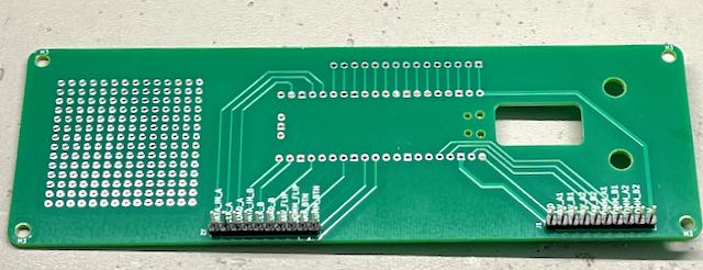
Photo 2 - Processor Board (Top)
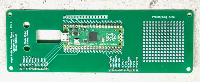
Photo 3 - Processor Board (Bottom)
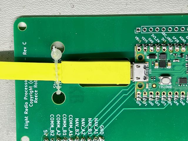
Photo 4 - Cable Strain Relief
Flight Radio Software
The software required to realise this project includes:
-
the firmware to run the LED displays and read the inputs from the two transfer buttons and two dual rotary encoders
-
an X-Plane plug-in to connect with the flight radio (custom HID device) and interface with the flight simulator.
The next two sections provide more detail.
Firmware
The firmware requirements were met by using circuitpython... well almost. I did however need to submit a patch to that project to support custom HID devices. But once that was accepted, circuitpython had all the functionality I needed.
I leveraged the MAX7219 serial seven segment LED display driver IC for the four LED display banks. I wrote a display driver to format and display radio frequency values. For the 7 Segment digits, I chose 0.28 inch common cathode LED displays in 3 and 2 digit modules to make a total of 5 digits per frequency display. Using the small size helped achieve the desired minimum size for the overall width dimension.
I also wanted to support the ability to have multiple flight radios in the stack. To achieve this the firmware provides the ability to configure the radio as “Radio 1" or “Radio 2" allowing a total of two radios in X-Plane. (This is the configuration I use in my panel.) By default the radio is configured to act as Radio 1. If you press the Nav encoder button it will toggle the designation to Radio 2. Once you do that, you need to reset the radio by unpluging it and plugging it back in again to have it identify as the selected radio. You can toggle back to Radio 1 again and repeat the reset procedure. The setting you choose will be remembered by the radio until you change it.
The firmware presents the radio as a custom USB HID device to the flight simulation host computer. The X-Plane plugin integrates the flight radio(s) to the simulator.
X-Plane Plugin
The other part of the software is the X-Plane plugin that works with the flight radio HID device. This plugin is largely based on the project created by PaulStoffregen & Jorg Neves Bliesener and is used to communicate between the flight radio firmware and the flight simulator. Transfer button inputs and rotary encoder values are sent to the simulator and radio frequency values and panel lights state received and used to control the display brightness (lower for night flights).
I am a Mac user (that is a big reason I use X-Plane 😉) so I have compiled and tested the plugin on my machine. There was a bug in the original project that I fixed in my fork of the codebase. Using Ubuntu Linux, I compiled the linux and windows versons which are included in the download. The windows version has been tested on Windows 10 Home. The linux version is not tested as I don’t have the hardware for it. If you run X-Plane on Linux I would love to hear from you if you get that version working or not?
To install the plugin unzip the attached plugin archive file in the X-Plane plugins directory. The “FlightControls” folder should end up in the X-Plane plugins directory.
If there is enough interest I will provide the source code of the plugin so anyone can help with the builds for the various platforms.
Note: If the macOS Gatekeeper is blocking the plugin, you can bypass Gatekeeper for this specific instance.
1. Open Terminal:
You can find Terminal in Applications > Utilities.
cd /path/to/X-Plane/Resources/plugins/FlightControls
2. Navigate to the Plugin Directory:
Use the cd command to navigate to the directory containing the mac.xpl plugin. For example:
xattr -d com.apple.quarantine mac.xpl
Assembly
| Id | Designator | Package | Quantity | Designation | Supplier and ref |
|---|---|---|---|---|---|
| 1 | SW2,SW1 | SW Cherry MX 1.00u PCB | 2 | SW Push | https://www.aliexpress.com/item/33007890748.html |
| 2 | SW4,SW3 | RotaryEncoder Alps EC12E Double Sided Vertical H20mm | 2 | Rotary Encoder | https://www.aliexpress.com/item/1005003474740730.html |
| 3 | C1,C2,C6,C5 | CP Radial D5.0mm P2.50mm | 4 | 10uF | |
| 4 | C3,C7,C8,C4 | C Disc D7.5mm W4.4mm P5.00mm | 4 | 0.1uF | |
| 5 | R1,R2,R3,R4 | R Axial DIN0411 L9.9mm D3.6mm P15.24mm Horizontal | 4 | 47K | |
| 6 | U1,U2,U3,U4 | DIP-24 W7.62mm Socket | 4 | MAX7219 | |
| 7 | U12,U8,U10,U6 | CC 0.28" 2seg | 4 | 2 bit Red Cathode | https://www.aliexpress.com/item/1005001861041699.html |
| 8 | 2.54mm pitch round holes round pins 1*40 female socket | 40 | Socket Pins | https://www.aliexpress.com/item/4001122376295.html | |
| 9 | U11,U5,U7,U9 | CC 0.28" 3seg | 4 | 3 bit Red Cathode | https://www.aliexpress.com/item/1005001861041699.html |
| 10 | DIP-16 W7.62mm Socket | 4 | Socket | ||
| 11 | JP1 | PinHeader 1x03 P2.54mm Vertical | 1 | USE DATA IN B | |
| 12 | JP2 | PinHeader 1x02 P2.54mm Vertical | 1 | Connect CLK Signal | |
| 13 | JP3 | PinHeader 1x02 P2.54mm Vertical | 1 | Connect Load Signal | |
| 14 | JP4 | PinHeader 1x02 P2.54mm Vertical | 1 | Connect Data Signal | |
| 15 | J2,J1 | PinSocket 1x10 P2.54mm Vertical | 2 | Interconnect 01x10 |
Assemble the two circuit boards starting with the low profile parts and working your way up to the rotary encoders.
Note: The 7-Seg LED modules are socketed on the board. This is necessary to raise the height of the modules to position them just below the face panel cutouts (referr photos 5 & 6 to see the physical arrangement). The 3 digit module uses the DIP socket and the 2 digit module uses two rows of socket pins - 5 each side.
When completed, the two PCB’s are stacked in a sandwich with spacers providing support between the them. On top of this a 3D printed faceplate is secured with another set of smaller spacers. Use M3 spacer posts, bolts and nuts as required.
Print the Faceplate, knobs, rings & buttons provided in the 3D Print STL files archive. The small dummy “PULL TEST" and “PULL IDENT" knobs should be glued an the positions provided in the faceplate. Glue the light grey coloured rings onto the frequency knobs to provide visual contrast as shown in the phtots 5 & 6 below
The faceplate was printed with two filament colours by configuring the print to pause before the surface detail layer to allow for a filament change to light grey.
Mount the flight radio(s) into your panel. For my panel I printed small brackets that connected to the mounting holes of the processor PCB with screw holes at the front to fix to the back of the flight panel (see photo 7 below).
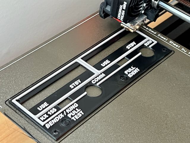
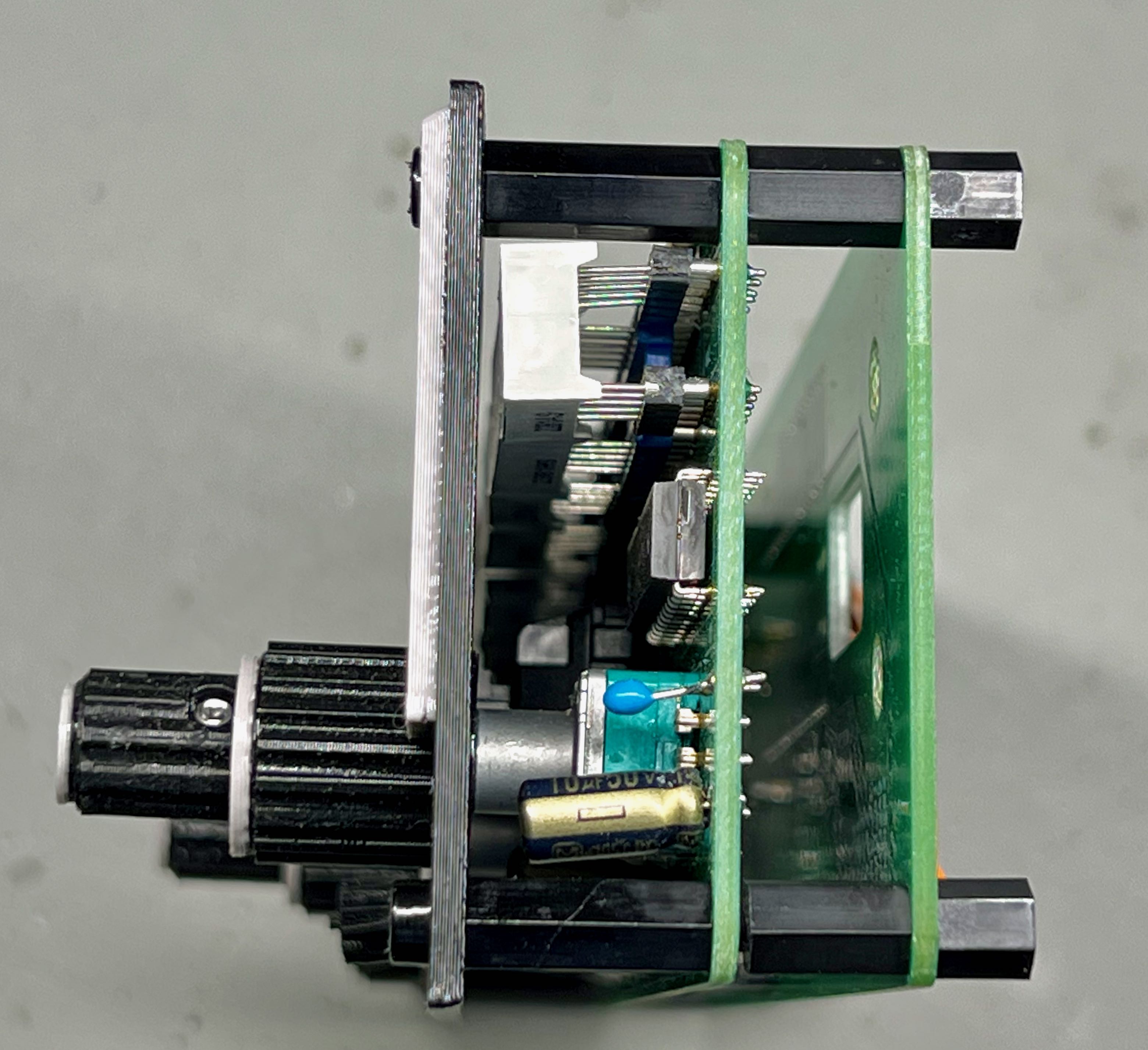
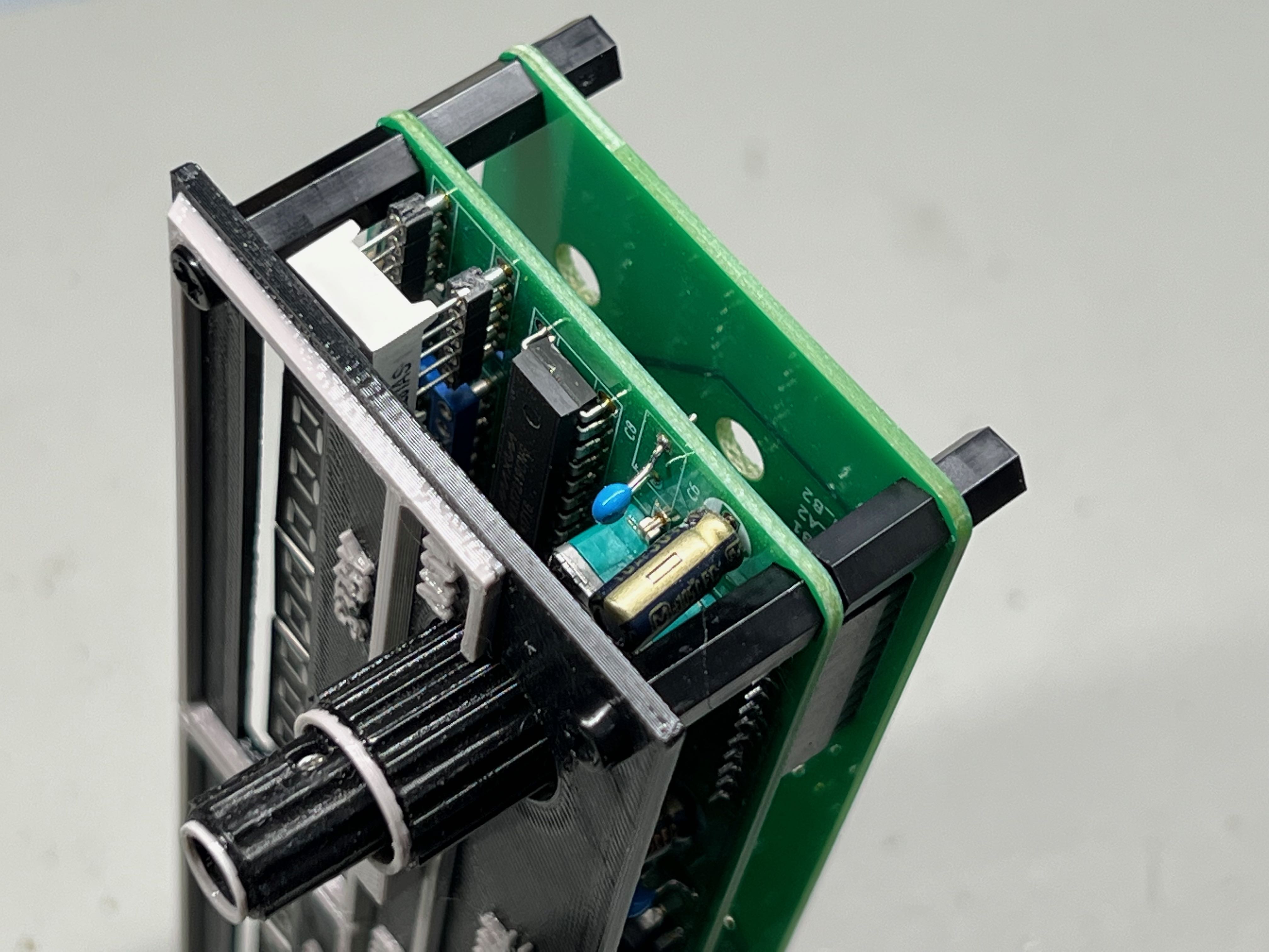
Photo 5 & 6 - Complete Board and Faceplate Assembly
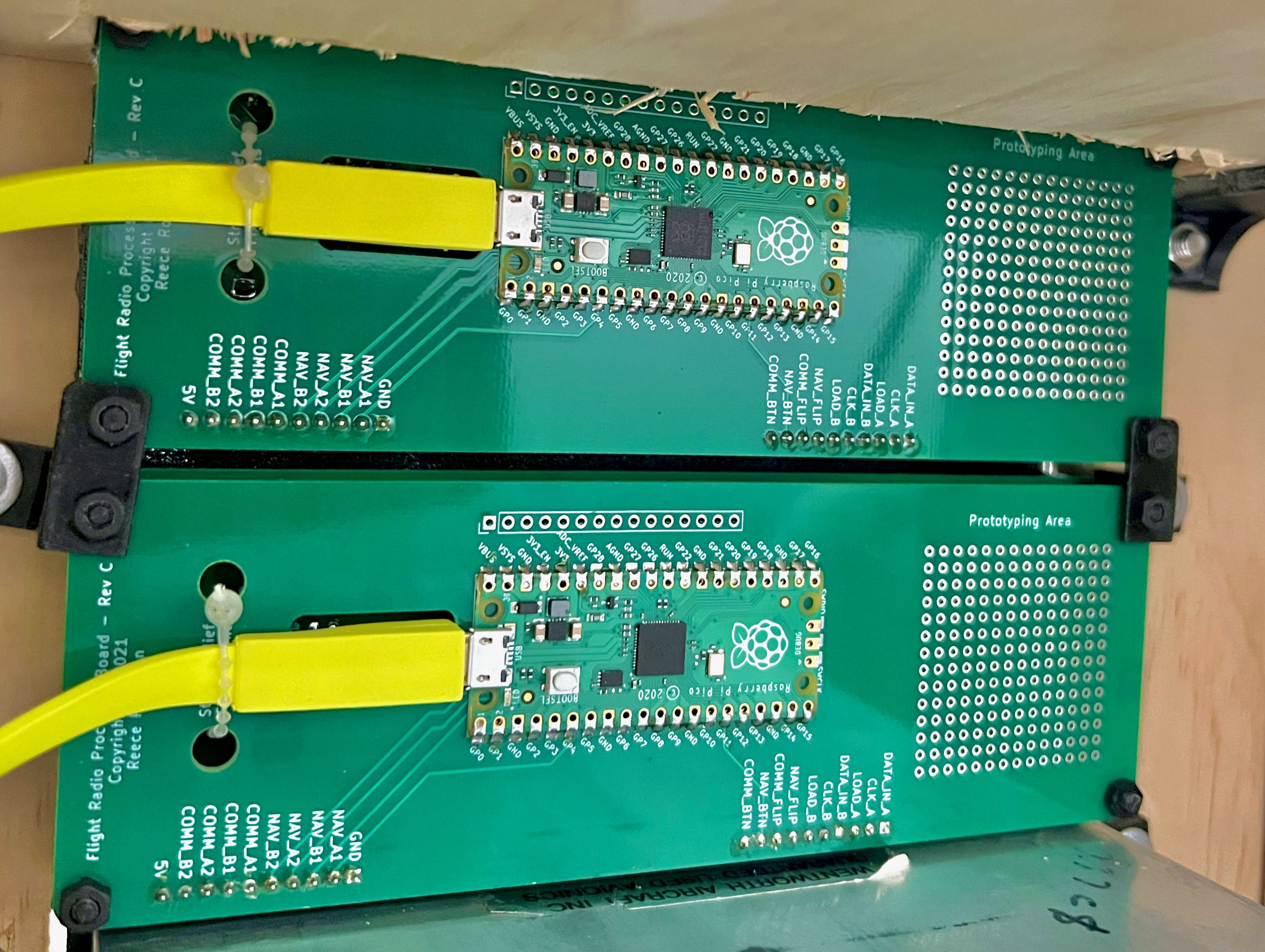
Photo 7 - Mounting Bracket View
